Local Monitor - standalone
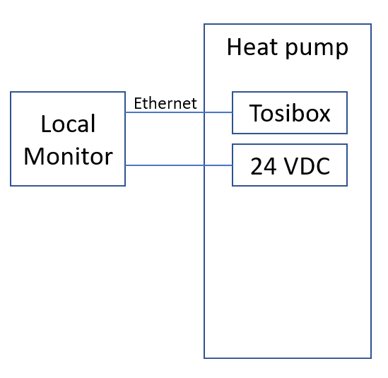
Local Monitor can be provided as a standalone solution. Along with the software, a hardware package will be provided that can be place in the same network with the heat pumps. If possible, install the standalone Local Monitor unit inside the heat pump’s electrical cabinet.
Connect the Local Monitor unit to a 5 Vdc 3 A USB type C power supply.
Connect an Ethernet cable between the Local Monitor unit and the heat pump’s Tosibox unit (or other suitable router). Use one of the LAN ports (not the WAN or Service port) on the Tosibox unit.
Network settings
The standalone solution IP address can be found in the settings menu shown below
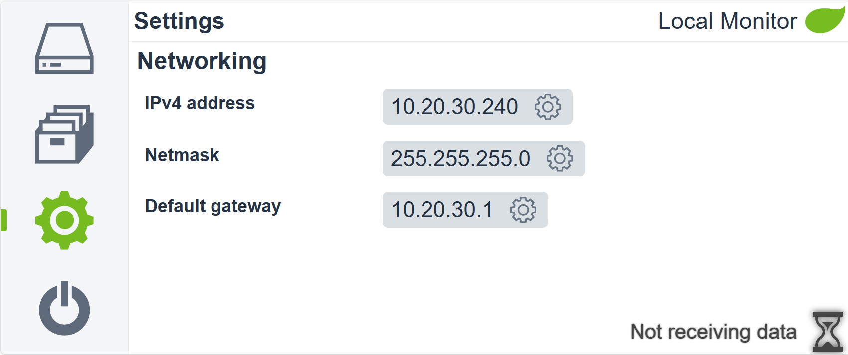
The default network settings settings are configured to be compatible with the default ChillHeat heat pump network settings. If the heat pumps are connected to a network with custom settings then the network settings of the Local Monitor must be adjusted as well. In order to do this:
Open the network settings by pressing the highlighted button shown in the image above
Change the IPv4 address, Netmask and Default gateway
Note
If you change the IP address of the Local Monitor, make sure to update the IP address in the heat pump automation
Verifying that the Local Monitor is collecting data from the heat pumps
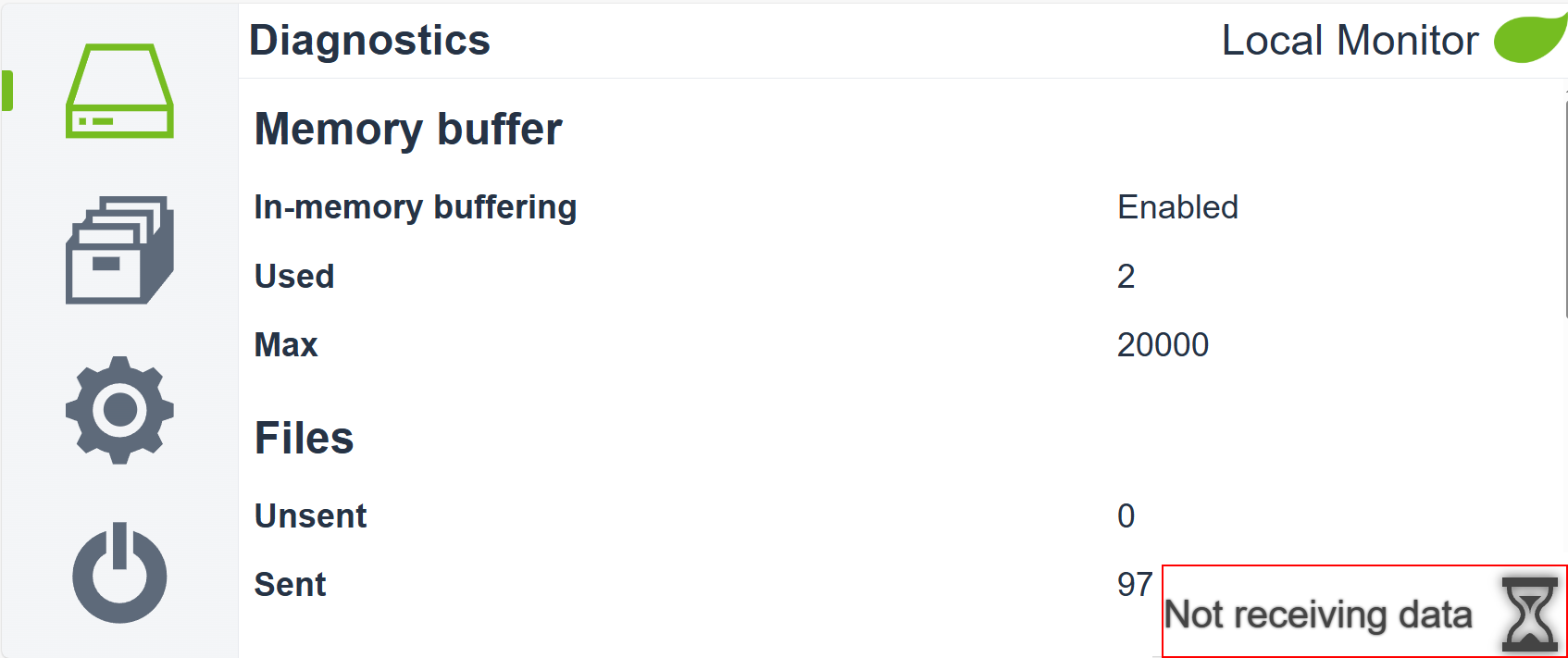
To verify that the Local Monitor is working and actually collecting data, look at the symbol in the bottom right corner. If the symbol is a gray hour glass and says Not receiving data, then the Local Monitor is not receiving data.
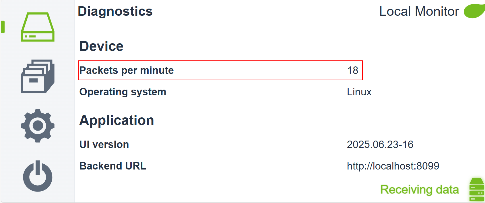
If the symbol is a green server and says Receiving data, then the Local Monitor is receiving data.

You can also verify that the Local Monitor is receiving data by checking the Packets per minute value in the Diagnostics page. The value of the Packets per minute is above 0 when data is being received
Diagnostics
The diagnostics page contains the following information about the Local Monitor:
Memory buffer
In-memory buffering: Enabled or disabled. If enabled, the data packets are stored in RAM before being flushed into persistent memory. If disabled, the data packets are written into persistent memory immediately. In-memory buffering reduces writes to the permanent memory, thus increasing its lifespan.
Used. How many data packets are currently stored in the memory buffer.
Max. How many data packets can be stored in the memory buffer before being flushed to the permanent memory.
Files
Unsent. How many data packets are currently stored without having been sent to the cloud.
Sent. How many data packets have been sent to the cloud.
Free space
Unsent folder. How much free space remains in the unsent folder.
Sent folder. How much free space remains in the sent folder.
Space to keep available. How much free space will be kept available in the permanent memory. If the available free space drops below this limit, the oldest collected data packets will be deleted.
Device
Packets per minute. How many data packets per minute the Local Monitor is receiving.
Operating system. Operating system of the Local Monitor.
Application
UI Version. Version of the User Interface.
Backend URL. URL for the backend endpoints.
Installing on an existing computer
Local Monitor can be installed on an existing computer on the same network with the heat pumps. Supported operating systems include Windows 32 and 64 bit, Linux 32, 64 bit, arm32, and macOS. Acquire a suitable installer package and install it in the computer like you would any software.
The installer will install a service that will automatically start when the computer starts.
On Windows, a firewall rule must be created to allow network access for Local Monitor.
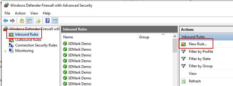
Open the Windows Defender Firewall settings.
Click on Inbound Rules and on New Rule…
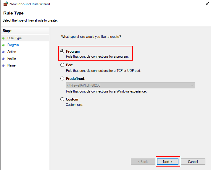
Select Program, and click on Next.
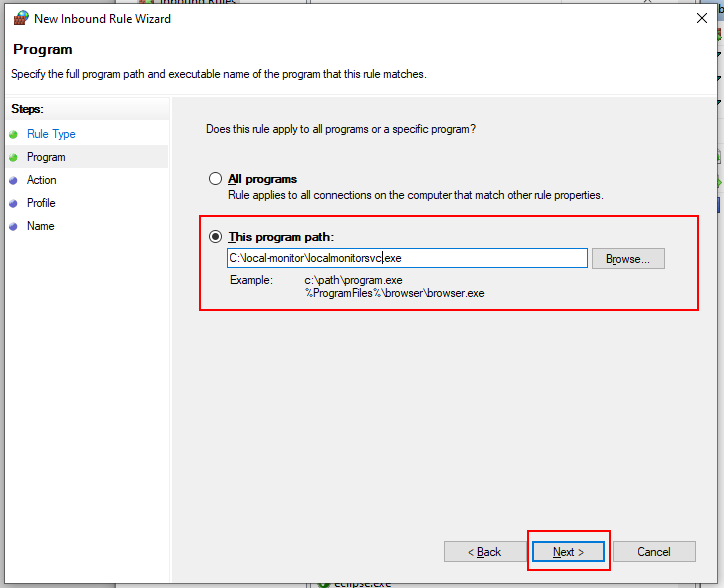
Browse to the Local Monitor installation folder, and select localmonitorsvc.exe. Click Next.
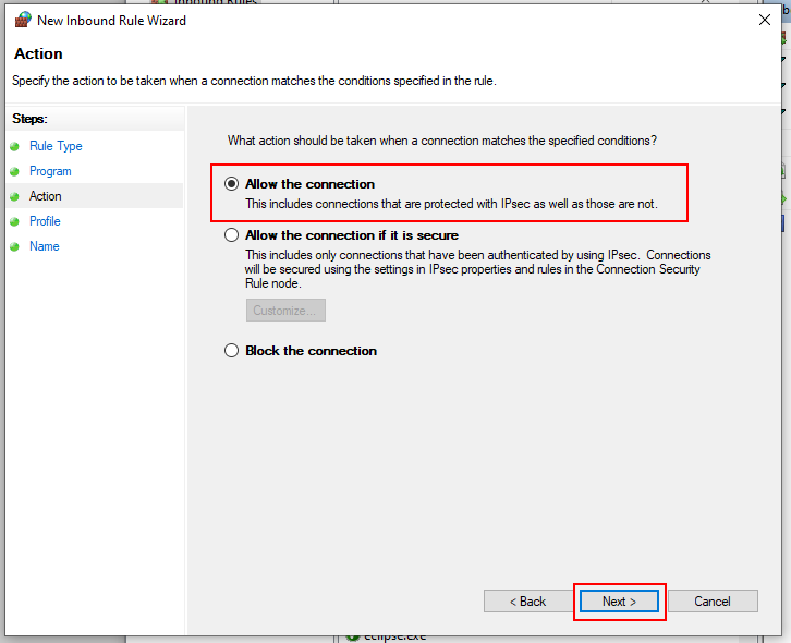
Select Allow the connection, and click Next.
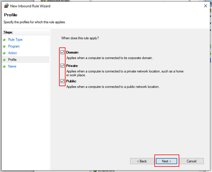
Select all boxes, and click Next.
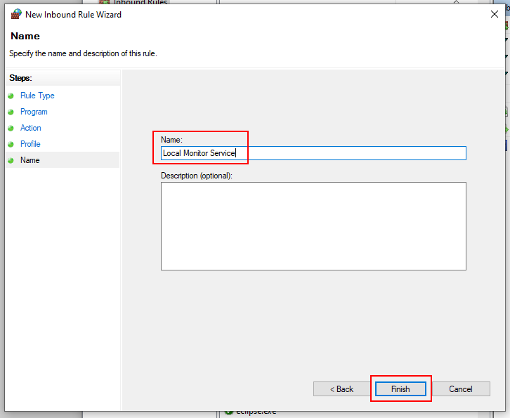
Give a name for the rule, such as Local Monitor Service, and click Finish.
You must create an outbound rule as well by repeating the steps, but instead of creating a new Inbound rule, select Outbound rules from the menu on the left.
Verifying that the Local Monitor is collecting data from the heat pumps
To verify that the Local Monitor is working and actually collecting data, check Verifying that the Local Monitor is collecting data from the heat pumps
Changing the collected data folder
By default, the collected data is saved to folders C:\temp\local-monitor\unsent and C:\temp\local-monitor\sent.
To change the folder where the unsent and sent data is stored:
1. Edit the localmonitor.vmoptions and localmonitorsvc.vmoptions files found in the installation folder. Add the following lines:
-Doilon.odp.persister.unsentFolder=C:\local-monitor\unsent
-Doilon.odp.persister.sentFolder=C:\local-monitor\sent
Replace the folders C:\local-monitor\unsent and C:\local-monitor\sent with folders of your choosing.
Restart the Local Monitor.
Disabling RAM buffer
By default, the received data points are stored in a RAM buffer until 10,000 of them have been received. To have the data points stored to disk straight away, modify the localmonitor.vmoptions and localmonitorsvc.vmoptions files found in the installation folder.
Add the following line to both files:
-Doilon.odp.persister.bufferInMemory=false
Changing the IP address of Local Monitor in the heat pump automation system
By default, the heat pumps are configured to use the IP address 10.20.30.240 for the Local Monitor. If any other IP address is used, update the address in the heat pump automation PLC.
Uploading data
Uploading by connecting the Local Monitor to the internet
The Local Monitor will automatically upload data to the Oilon Device Portal as long as it has an internet connection. In order to connect the Local Monitor to the internet, plug in the computer or standalone version running the Local Monitor to a router. Ensure that the IP Settings are compatible with the router’s IP settings.
Uploading data by connecting to the Local Monitor with OHPC
If the Local Monitor cannot be connected to the internet, another way to upload the data is by connecting to it with OHPC.
Uploading data by manually moving the data to your computer
If the Local Monitor is installed into a computer and you are not able to connect to the Local Monitor with your laptop, move or copy the data from the Local Monitor to your laptop first. After moving the data, you can upload it to the Oilon Device Portal with OHPC.
Frequently asked questions
I have connected power to the standalone Local Monitor, but the screen remains black.
The power supply may not be strong enough. Ensure that it can provide at least 3 A and 5.0 Vdc.
I have connected power to the standalone Local Monitor. It is powered on but there is a blank white screen
The Local Monitor must be plugged into a network for the UI to show. The network does not need an internet connection.
How do I know if the Local Monitor is receiving data?
For the standalone version, check Verifying that the Local Monitor is collecting data from the heat pumps
For the computer version, check Verifying that the Local Monitor is collecting data from the heat pumps
How do I upload data from the Local Monitor?
Check Uploading data