General
Below are instructions on how to set operating conditions, add heat pumps, and how to use different functions to set up your heat pumps system for calculation.
Setting operating conditions
Changing refrigerants
Setting compressors to part load
Connecting heat pumps in series
Checking if the installation space has a sufficient volume
When using flammable refrigerants (such as R1234ze), the installation site must have a sufficient volume. In cramped spaces, a ventilated enclosure is required.
To check if the volume of the installation space is sufficient:
Select the heat pump model.
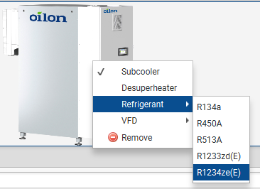
To select the refrigerant, right click on the heat pump image. Select Refrigerant and select the refrigerant from the list.
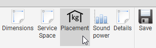
Click the Placement button.
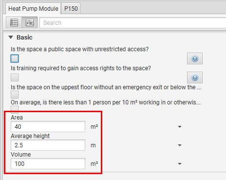
Select the applicable options and enter the area and average height of the space, or enter the volume of the space directly.
Open the second tab (P150 in the image). Compare the refrigerant charge with the maximum allowed charge.
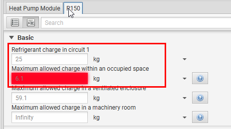
If the refrigerant charge is greater than the maximum allowed charge, a ventilated enclosure is required. See add a ventilated enclosure for a heat pump.
Reference standards
- Refrigerant charge limits and formulas
EN378-1 Annex C
Adding a ventilated enclosure for a heat pump
Sound levels
Sound levels at specific operating points
Unfortunately, it is currently not possible to estimate sound levels at specific operating points. The best available information is provided by the Oilon Selection Tool. The estimated sound levels vary by 3 dB(A) depending on the operating conditions.
Minimum allowed flow through the heat exchangers
For ChillHeat heat pumps that use plate heat exchangers (P30 - P450, RE210 - RE420, S180 - S580), there is no minimum required water/brine flow. If the flow is small enough to cause issues with heat transfer, the effect is taken into account in the heat exchanger simulation (the performance of the heat pump will degrade).
Contact Oilon HQ to check the minimum allowed water/brine flow of ChillHeat heat pumps that use shell and tube heat exchangers.
Maximum allowed flow through the heat exchangers
By default, the maximum allowed flow through the heat exchangers is defined so that the flow velocity is < 5.5 m/s in the heat exchanger connections. The purpose of the limit is to prevent the possibility of erosion in the heat exchanger connections. You will receive a warning if the flow velocity exceeds this limit. However, the limit is not absolute and exceptions can be made. A greater flow can be allowed if the water can be determined to be free of solid particles, such as sand or metal particles. If, for example, a water analysis has been conducted and the water is determined to be free of solid particles, the maximum allowed flow can be increased.
Connection modules
Connection modules allow you to make creative connections in the condenser or evaporator water circuit.
Condenser connection modules
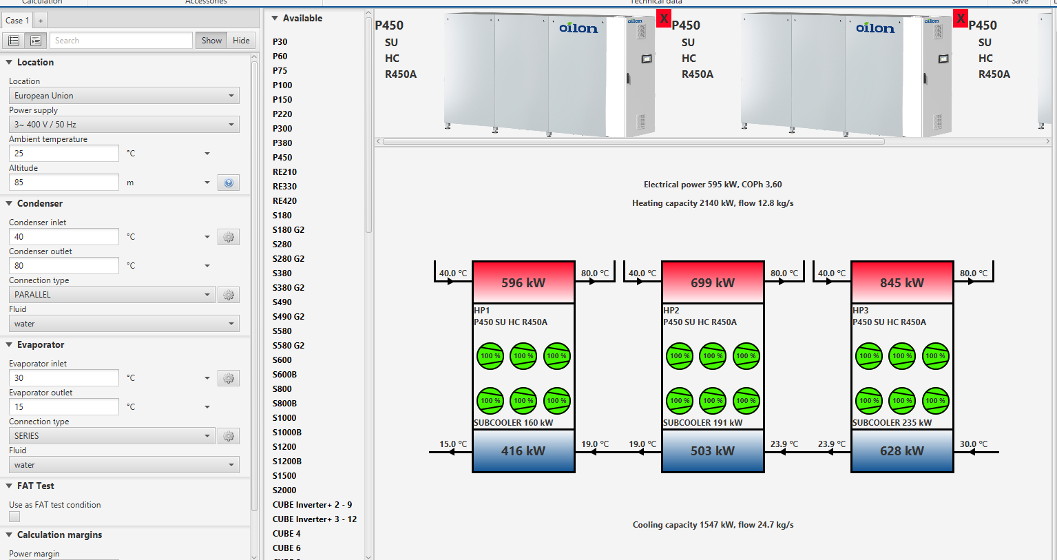
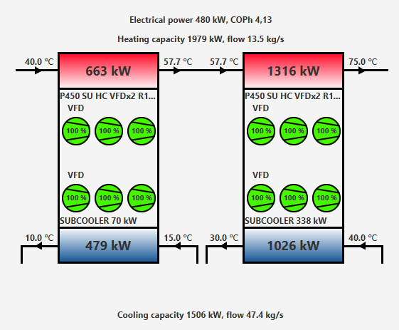
Connection modules can be used to create series or parallel connections between sets of heat pumps. An example below demonstrates how to create a connection between two parallel S series heat pumps and two P series heat pumps in series.
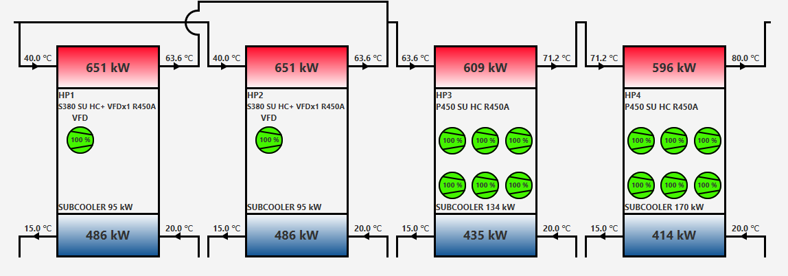
In order to create the connections shown above, follow the steps below.
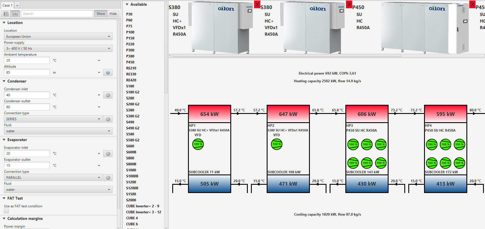
Insert your condenser temperatures and evaporator temperatures.
Select SERIES as the condenser connection type and PARALLEL as the evaporator connection type.
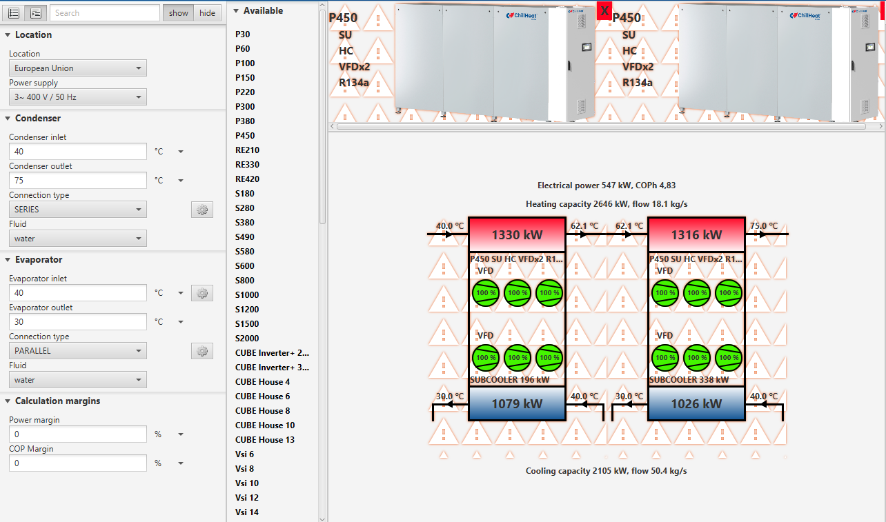
Select your heat pumps. Your selection should now look as shown below.
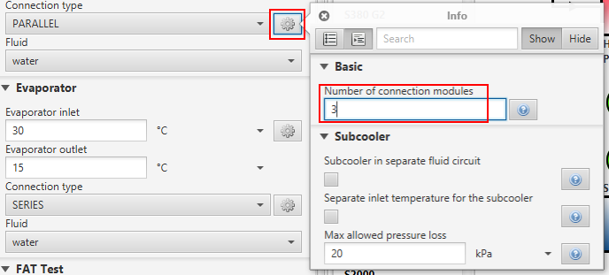
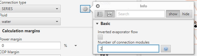
Click on the cog wheel on the condenser connection type and set the amount of connection modules.
Click on the Details button on the tool bar.

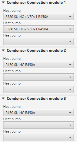
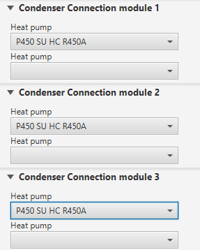
6. Scroll down to the connection module settings. Set the first and second heat pumps to the first connection module, the third heat pump to the second connection module and the fourth heat pump to the third connection module
Go back to the wireframe and calculate. Your selection should now look as shown below.
Individual temperatures
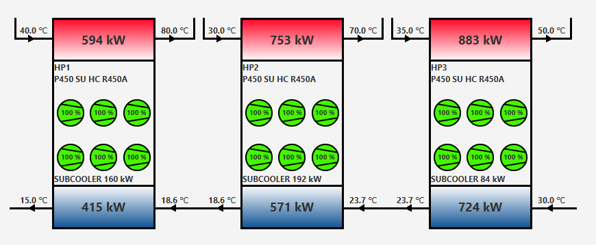
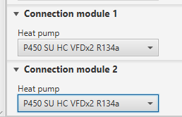
Connection modules can have individual inlet and outlet temperatures. This feature can be used for example when the heat pumps are connected to different heat sinks as shown in the image below.
In order to use the feature, follow the steps below.
Insert your condenser temperatures and evaporator temperatures.
Select PARALLEL as the condenser connection type.
Select your heat pumps. Your selection should now look as shown below.
Click on the cog wheel on the condenser connection type and set the amount of connection modules.
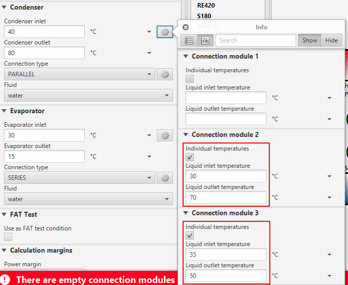
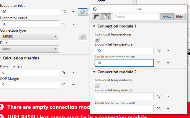
Click on the cog wheel on the condenser inlet temperature.
Enable individual temperature of the connection module 2 and 3
Set the inlet and outlet temperature for modules 2 and 3.
Click on the Details button on the tool bar.
9. Scroll down to the connection module settings. Set the first heat pump to the first connection module, the second heat pump to the second connection module and the third heat pump to the third connection module
Go back to the wireframe and calculate. Your selection should now look as shown below.
Evaporator connection modules
Individual temperatures
Connection modules can have individual inlet and outlet temperatures. This feature can be used for example when the heat pumps are connected to different heat sources as shown in the image below.
In order to use the feature, follow the steps below.
Insert your condenser temperatures and evaporator temperatures in the main evaporator circuit.
Select PARALLEL as the evaporator connection type.
Select your heat pumps. Your selection should now look as shown below.
Click on the cog wheel on the evaporator connection type and set the amount of connection modules.
Click on the cog wheel on the evaporator inlet temperature.
Enable individual temperature of the connection module 1
Set the inlet and outlet temperature for this circuit.
Click on the Details button on the tool bar.
9. Scroll down to the connection module settings. Set the first heat pump to the first connection module and the second heat pump to the second connection module.
Go back to the wireframe and calculate. Your selection should now look as shown below.
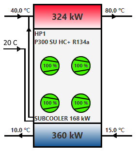
Subcooler with separate inlet temperature
The Subcooler with separate inlet temperature selection can be used if the subcooler of the heat pump is connected to a separate flow which will be merged with the condenser flow before entering the condenser. The connection is demonstrated in the image below. The inlet temperature to the heat pump is 40 °C, but there is a separate flow of 20 °C that is fed into the subcooler. Before the flow enters the condenser, the subcooler flow is merged to the condenser.
Part load graph
The part load graph can be used to check the part load performance and possible steps in the capacity control. The part load of P220 VFDx2 can be seen in the image below.
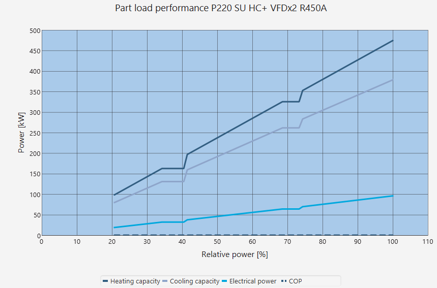
Let’s consider the P220 VFDx2 shown above. This is how the power control will work in practice, assuming we will start from a standstill and increase to full power:
The first VFD compressor is started at minimum load (60 %). The total power of the heat pump will be around 20 % (1 compressor = 100%, therefore 60/300 = 20 %)
The first VFD compressor will increase power to 100 %. The total power will be around 33 %.
Now when the power demand keeps increasing, but our compressor is running at 100 % power already, we cannot increase the power of the single compressor anymore. We can only start a new compressor. Therefore there will be a small hysteresis or step on the power output (kW) vs the control (%).
The second compressor will be started to minimum load of 60 % and at the same time the first compressor will reduce it’s power to 60 %. Therefore there will be a small step in the total power of the heat pump (from 100/300 to (60 + 60)/300 ie 33 % -> 40 %). This is represented as a step in the graph.
Both compressors will increase power until they are at full capacity.
The the last compressor will be started, and this is shown as the second step in the graph.
So the steps in the graphs are due to the fact that there will be a discontinuity in the power when starting a new compressor.
In practice this means that if the customer is asking for a power between 33 to 40 %, say 37 %, they will observe a fluctuation in the produced hot water or cold water temperatures. If their power demand is in the stepless capacity control regions, then the produced hot water or cold water temperatures will be more stable.
Compressor part load performance
Different types of compressors have different methods of part load control. The methods of part load control for the compressors in OST are
Variable frequency drive (VFD) for piston compressors
Variable frequency drive and slide control for screw compressors
Variable frequency drive (VFD) for residential scroll compressors, on/off for industrial scroll compressors
The method for calculating the part load performance (electrical power, cooling capacity, mass flow) is based on the performance data provided by the compressor manufacturers at different frequencies (if VFD control) or at different capacities (if slide control). The part load performance therefore is simply not a linear function of the part load compared to the full capacity performance. The performance differs from a linear relation because the internal efficiencies of the compressors are not constant, but instead vary slightly depending on the load.
For example, assuming a screw compressor with a full load electrical power of 100 kW at 60 Hz, the electrical power at 50 % is not simply 0.5 x 100 kW = 50 kW but instead slightly higher (eg 52 kW) due to lower efficiency at 30 Hz compared to 60 Hz.
In general, the part load performance is calculated with performance correction factors derived from the manufacturers’ data
where the \(X_{pl}\) is the performance (electrical power, cooling capacity, mass flow) at part load, \(X_{fc}\) is the performance at full capacity and \(f_{corr}\) is the performance correction factor, which is a function of the part load.