Electrical values of heat pumps
OST calculates several important electrical values for heat pumps. Below is a description of these values.
Electrical power
As the heat pumps utilize three phase alternating current, there are three key power values: actual electrical power, reactive power and apparent power.
Actual electrical power
Actual electrical power, sometimes called real electrical power or just electrical power, is the electrical power the heat pump takes from the grid and uses for work. This is typically the most interesting power since it is what is used to measure the electrical power consumption and it is used for calculating the power bill. It is typically measured in kW or horsepower (hp).
Reactive power
Reactive power of the heat pump is power that is taken from the grid and used to charge different capacitive or inductive loads, such as motor windings. The power is eventually returned back to the grid. Large industrial consumers typically must also pay a fee to the power utility company for the reactive power usage. Large reactive powers increase the total apparent power consumption and current draw from the grid. Therefore, it may sometimes be required to deploy methods to lower the reactive power consumption with different methods, such as reactive power compensation batteries or variable frequency drives. Reactive power is typically measured in kvar.
Apparent power
Apparent power of the heat pump is the total power, including the actual electrical power and reactive power. It is useful when designing the supply system components, such as transformers, for the heat pump. The apparent power is typically measured in kVA.
Currents
Below is a description of the most important currents of heat pumps. The currents are important when selecting the electrical supply system components, such as fuses.
Current at design point
Current at design point is the current that the heat pump will draw when operating at the selected operating conditions at the selected capacity. This current takes into account all the power consumption of the heat pump (including both compressors for the S600 - S2000 heat pump).
Starting current at design point
Starting current at design point is the current that the heat pump will draw when starting a compressor near full load at the selected operating conditions. The starting current will last for less than one second. The main supply fuses must be selected with this in mind.
The starting current is calculated as follows:
The heat pump is assumed to run at the selected operating conditions.
The heat pump is running with all but one compressor on.
If there are both VFD driven and non-VFD driven compressors, it is assumed that the last starting compressor is a non-VFD driven compressor.
The operating current of all the running compressors is calculated.
The starting current of the last non-running compressor is calculated.
All the currents are summed together to form the starting current at design point.
The starting currents for compressors are calculated with
where \(I_{oper}\) is the operating current of the compressor and \(f_{start}\) is a factor that depends on the starting mode of the compressor. The factors for different starting modes are
3 for partial winding, soft start and star-delta
5 for direct-on-line
1 for VFD
Current at the most demanding operating point
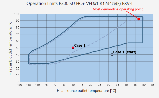
Current at the most demanding operating point is similar as the current at design point with the difference that the operating current is calculated at the most demanding operating point that the heat pump can operate at. The most demanding operating point is typically at the upper right corner of the allowed operation limits, as shown in the image below. The importance of the current at the most demanding operating point is discussed below.
Starting current at the most demanding operating point
Starting current at the most demanding operating point is similar as the starting current at design point with the difference that the starting current is calculated at the most demanding operating point that the heat pump can operate at. The most demanding operating point is typically at the upper right corner of the allowed operation limits, as shown in the image below. The importance of the current at the most demanding operating point is discussed below.
Minimum Circuit Ampacity
Minimum Circuit Ampacity (MCA) is the smallest continuous current (in amperes) that a conductor must be rated to carry safely under normal operating conditions. The calculation in OST is done according to the CAN/CSA 22.2 NO 60335-2-40:17/UL 60335-2-40 Annex 101.DVB.
Maximum Overcurrent Protection
Maximum Overcurrent Protection (MOP) specifies the largest fuse or circuit breaker rating allowed to protect a circuit without nuisance trips or equipment damage. The calculation in OST is done according to the CAN/CSA 22.2 NO 60335-2-40:17/UL 60335-2-40 Annex 101.DVB.
Minimum Circuit Ampacity at the most demanding operating point
Minimum Circuit Ampacity (MCA) at the most demanding operating point is similar as the minimum circuit ampacity at design point with the difference that the MCA is calculated at the most demanding operating point that the heat pump can operate at. The most demanding operating point is typically at the upper right corner of the allowed operation limits, as shown in the image below. The importance of the current at the most demanding operating point is discussed below.
Maximum Overcurrent Protection at the most demanding operating point
Maximum Overcurrent Protection (MOP) at the most demanding operating point is similar as the minimum circuit ampacity at design point with the difference that the MOP is calculated at the most demanding operating point that the heat pump can operate at. The most demanding operating point is typically at the upper right corner of the allowed operation limits, as shown in the image below. The importance of the current at the most demanding operating point is discussed below.
VFD currents
VFD input current
VFD input current is the current that is drawn by the VFD from the supply.
Typically the VFD input current is required only by Oilon engineers, since the VFD supply is typically connected to the main control panel of the heat pump. The VFD input current is relevant in some design situation, such as when designing an appropriate fuse and cable size for the S600 - S2000 heat pumps. For S180 - S580 heat pumps the VFD input current is almost the same as the heat pump current at design point, and the heat pump current should be used instead when selecting fuses.
Error
The VFD input current must not be used to select the VFD size. The VFD input current will always be smaller than the current draw of the compressor motor. It is the current draw of the compressor motor that must be used when selecting a suitable VFD size.
Maximum VFD input current
Maximum VFD input current is similar as the VFD input current with the difference that the maximum current is calculated at the most demanding operating point that the heat pump can operate at. The most demanding operating point is typically at the upper right corner of the allowed operation limits, as shown in the image below. The importance of the current at the most demanding operating point is discussed below.
Error
The VFD input current must not be used to select the VFD size. The VFD input current will always be smaller than the current draw of the compressor motor. It is the current draw of the compressor motor that must be used when selecting a suitable VFD size.
Compressor motor currents
Compressor current at design point
The compressor current at design point is similar as the heat pump current at design point but for a single compressor. Typically this value is required only by Oilon engineers. For the S600 - S2000 heat pumps, this value is required when selecting appropriate cable sizes between the VFD and the compressor.
Compressor current at the most demanding operating point
The compressor current at the most demanding operating point is similar as the heat pump current at the most demanding operating point but for a single compressor. Typically this value is required only by Oilon engineers. For the S600 - S2000 heat pumps, this value is required when selecting appropriate cable sizes between the VFD and the compressor.
Supply cable currents
Cable allowed current
The cable allowed current is the maximum allowed current that can flow in the compressor supply cables without compromising the integrity of the supply cable. The allowed current is dependent on various factors, such as the cable size, installation type, and surrounding temperature. The allowed current should be higher than the current draw of the compressor motor.
Current per supply cable at design point
The current per supply cable at design point is the current draw of the compressor motor divided into each supply cable. Some compressors have only one supply cable, while others may have two. In case of a partial winding start mode, the current per supply cable may be asymmetric; one motor winding may draw more current than the other. In such case the current shown in this parameter is the higher of these currents.
Other electrical values
VFD power loss
VFD power loss denotes the amount of power lost as heat in the VFD. As VFDs are never 100 % efficient, a part of the input power will be lost as heat to the surrounding air. The VFDs used by Oilon typically have an efficiency of 97.5 %. The VFD power loss must be considered when designing the ventilation system heat load of the surrounding room.
What is the difference between the design point current and current at the most demanding operating point?
The difference between the design point current and the current at the most demanding operating point is
The current at design point is calculated at the user specified operating point at the user specified part load.
The current at the most demanding operating point is calculated at the most demanding operating point (with respect to current draw) of the heat pump’s allowed operating range. The current is calculated at full capacity.
Why are the most demanding currents important?
Oilon always informs both the currents at the selected design point and the currents at the most demanding operating point. The currents at the most demanding operating point are important to know when designing the electrical supply of the heat pumps. Supply components, such as transformers, fuses and supply cables, must be selected so that they can withstand not only the currents at design point but also the currents at the most demanding operating point if it is foreseen that the heat pump may operate in the most demanding point. If the electrical supply system is designed only for the design point currents, and the customer wants to operate at different, more demanding, operating points in the future, it may not be possible due to insufficiently sized electrical supply components, such as fuses and cable sizes. If the customer will never want to operate at more demanding operating points, then the currents at the most demanding operating points may not need to be considered.
In conclusion, if it is at all possible that the heat pump may operate at operating points that are more demanding than the design point, it is important to consider the currents at the most demanding operating point when designing the electrical supply system. If the heat pump will never operate at more demanding operating points than the design point, the most demanding operating point currents need not be considered.
For example, in the case shown below, the current at design point for the P300 SU HC+ VFDx1 R1234ze(E) heat pump at the user specified design point (Case 1 in the image) is 167 A. In this design point, a 200 A fuse size would be suitable. However, the current at the most demanding operating point (upper right corner of the operating limits chart) is 328 A. Therefore, if a 200 A fuse has been selected, the heat pump will not be able to operate at full capacity in the most demanding operating point. Should the customer at some point want to do this, they would have to increase the fuse and cable sizes to accommodate the increased current draw. Therefore, if it is possible that the customer may want to operate the heat pump at these more demanding operating points at some point in the future, it may be beneficial to consider the current at the most demanding operating point early on in the project design.
Elecframes
The elecframes are simplified diagrams of the heat pump electrical supply connections. The diagrams show the main power connections an distribution from the grid to the compressors. The parts surrounded with dashed lines are outside the scope of Oilon delivery.
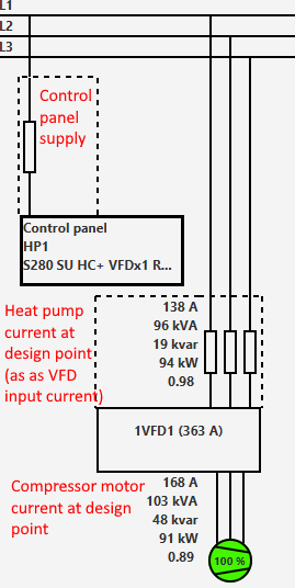
P and RE series
The P and RE series require one supply connection to the control panel of the heat pump. Separate control voltage supply is not required. The image below shows the different currents in the heat pump. The heat pump current at design point (and most demanding operating point) are required by the customer to select appropriate fuse and cable sizes.
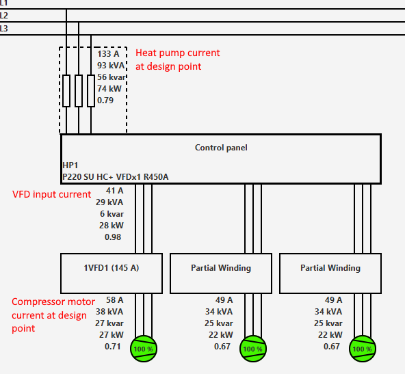
S180 - S580
The S180 - S580 heat pumps require a supply connection to the motor starter (VFD) of the heat pump. Moreover, a separate control voltage supply is required to be connected to the control panel. The image below shows the different currents in the heat pump. The heat pump current at design point (and most demanding operating point) are required by the customer to select appropriate fuse and cable sizes.
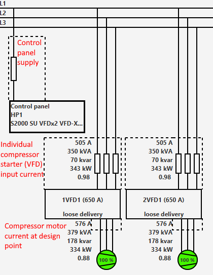
S600 - S2000
The S600 - S2000 heat pumps require separate supply connections to both of the motor starters (VFD/soft starter) of the heat pump. Moreover, a separate control voltage supply is required to be connected to the control panel. The image below shows the different currents in the heat pump. The compressor motor starter input currents (VFD input currents) are required by the customer to select appropriate fuse and cable sizes.
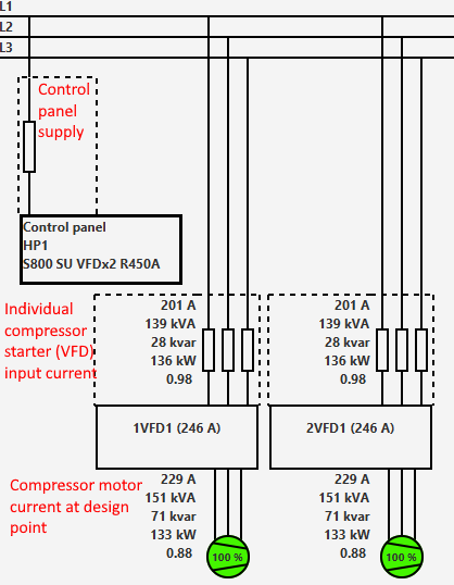
In cases where the selected VFD (or soft starter) is too large to be attached to the heat pump frame, it will be delivered loose. In these cases the customer must also provide the cabling between the VFD (or soft starter) and the compressor. For selecting appropriate cable size between the VFD and compressor, the compressor motor current must be used.