Operational limits of heat pumps
The operational limits of heat pumps define areas within which the heat pumps are allowed to be operated. Typically these areas as shown as functions of evaporator and condenser temperatures. The most common operational limit is the operation envelope (sometimes called temperature envelope, or simply envelope) of the compressor. However, a heat pump consists of more components than just the compressor, and therefore the operational limits of all other components must be considered. Currently, the operational limits of different components can be visualized with the charts buttons in the menu bar:
The different charts are:
Operation envelope: The operation envelope chart shows the operational limits of the compressor
Operation limits: The operation limits chart shows the operational limits of the compressor and the expansion valve.
Fuse selection: The fuse selection chart shows the operational limits for different fuse sizes.
VFD Operation Limits: The VFD operation limits chart shows the operational limits for different variable frequency drives (VFDs).
Ambient temperature: The maximum allowed ambient temperature for the selected heat pump configuration.
Note
All of the charts must be inspected to determine the allowed operational limits of the selected heat pump configuration.
Operating points in the charts
There may be three different types of operation points shown in the charts
Operating point: The selected operating point of the selected case.
Min: If there are more than one heat pump in the selection, the min point is the operating point in the minimum capacity situation when all the other heat pumps are turned off.
Start: The starting operating point after a long standstill of the heat pump. The process waters are assumed to have cooled down or warmed up to the same values as the inlet temperatures.
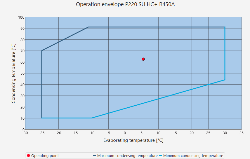
Operation envelope
The most common operational limit chart is the operation envelope. This is the same chart used by compressor manufacturers to show the allowed operational limits of the compressor. No other components are considered. The operation point must be within the area defined in the chart.
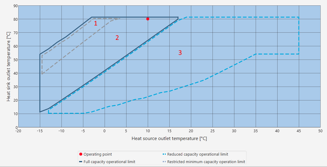
Operation limits chart
The operational limits chart shows the operational limits of the compressor and expansion valve. The selected expansion valve will determine the upper and lower limits of the refrigerant flow. If the selected expansion valve is too small, the heat pump may not be able to operate at full capacity. If the selected expansion valve is too big, the heat pump may not be able to operated at the stated minimum capacity. If there are multiple operation points, often a compromise between maximum capacity and minimum part load must be made. The different areas of operation are shown in the chart:
Restricted minimum capacity operational limit: The minimum allowed part load in this area is higher than the absolute minimum possible part load of the compressors. For example, if the compressors would allow a part load of 25% for the heat pump but the operating point is in this area, the minimum allowed part load may increase from 25% to 35%. The minimum part load is limited by the super heat control and expansion valve; a stable superheat must be ensured to ensure a long lifetime for the heat pump.
Full capacity operational limit: The heat pump can be operated at full (100%) capacity in this area.
Reduced capacity operational limit: The heat pump can operate in this area. However, you will not achieve the full power output as predicted by OST. In this area, the selected expansion valve is too small, leading to a restricted flow of refrigerant and to a power output reduction.
Full and reduced capacity overlapping area: The overlapping area is the most difficult to calculate accurately, as it is affected by the calculation accuracies of all three main components: the compressors, the heat exchangers, and the expansion valves.
For the S series heat pumps there are two additional areas
Oil cooling required: If the operation point is within this area, the oil cooling option must be selected. Otherwise the discharge gas temperature will be too high.
Oil cooling and liquid injection: If the operation point is within this area, the oil cooling and liquid injection options must be selected. Otherwise the discharge gas temperature will be too high.
Note
Sometimes the start point may be within the Reduced capacity operational limit; this is fine, since the start of the heat pump will be done gradually and not at full capacity. However, it must be ensured that the operating point moves to be within the allowed operating areas within a couple of minutes during the startup.
Fuse selection
The fuse selection chart shows the operational limits for different fuse sizes. The fuse in question is the fuse between the heat pump and the customer’s supply. The fuse selection chart has different areas for different fuse sizes. The operating point of the heat pump determines which fuse size is large enough. The minimum capacity situation must also be considered.
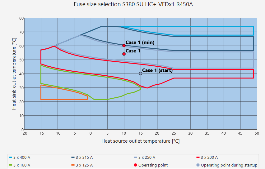
In the chart above, the main operating point is within the 3 x 250 A fuse area. This would mean that the 250 A fuse (or larger) could be selected as the fuse size. However, the minimum capacity operating point is slightly outside the 250 A area. In order for the fuse size to be large enough for the minimum capacity operation, the 315 A fuse must be chosen.
It is recommended to use the maximum fuse size shown in the chart. In the chart above, this would be the 400 A fuse. Following this recommendation ensures that if in the future the operating points differ from the operating points mentioned during the sales (for example, the heat pump is required to produce hotter water), then the electrical supply will not be limiting the operation.
Note
The marking 3 x 250 A refers to a fuse size of 250 A per each supply phase, so 3 fuses in total, 1 per supply phase.
Note
A larger fuse size can also be selected. For example, if the operation point is in the 250 A fuse area, a 315 A fuse can be used.
Note
The supply cable size must always be dimensioned according to local laws and regulations.
VFD operation limits chart
The VFD operation limits chart shows the operational limits for different VFD sizes. The VFD operational limits chart has different areas for different VFD sizes. The operating point of the heat pump determines which VFD size is large enough. The minimum capacity situation must also be considered.
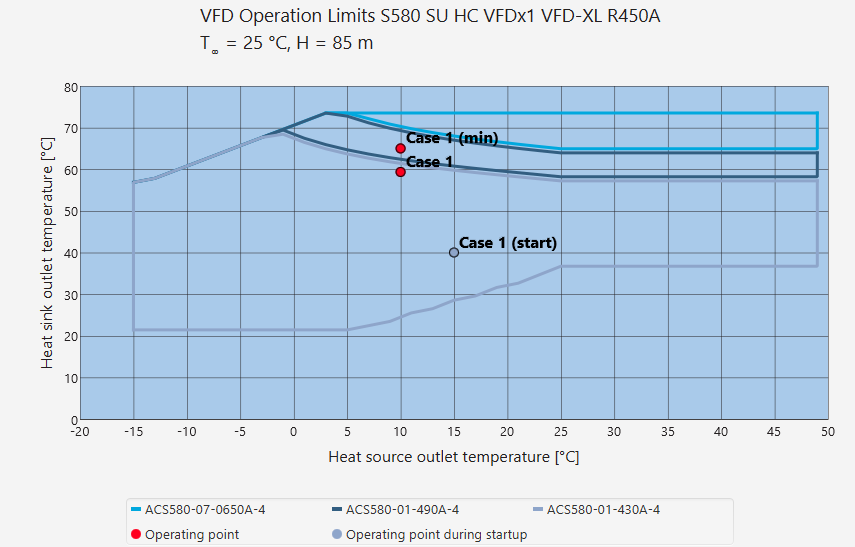
In the chart above, the main operating point is within the 430 A VFD area. This would mean that the 430 A VFD (or larger) could be selected as the VFD size. However, the minimum capacity operating point is slightly outside the 430 A area. In order for the VFD size to be large enough for the minimum capacity operation, the 490 A VFD must be chosen.
Note
A larger VFD size can also be selected. For example, if the operation point is in the 430 A VFD area, a 490 A VFD can be used.
Warning
Oilon recommends selecting a VFD that will cover the whole operational area of the heat pump. If a smaller than the recommended size is selected, the heat pump cannot be operated in operating conditions where a larger VFD would be required, not even on part load. Select a smaller VFD only if you are sure you will never need the full operational area.
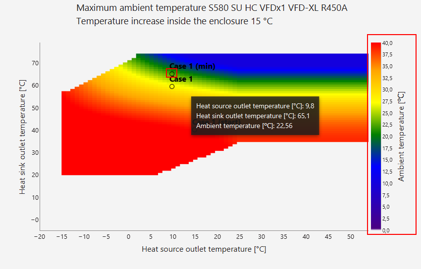
Ambient temperature
The ambient temperature chart shows the maximum allowed ambient temperature of the selected heat pump configuration. The maximum allowed temperature is dependent on the compressor types, supply cable sizes and installation types, enclosure temperature rise and operation points. The maximum allowed temperature can be read from the chart either by moving your mouse over the operating point, or by checking the different values of different colors from the right side of the chart.
For example in the chart below, the maximum allowed ambient temperature in the Case 1 (min) operating point is roughly 22.5 C.
Evaporator water/brine temperatures
There are limits for both the inlet and outlet water/brine temperatures of the evaporator.
The maximum allowed inlet and outlet temperatures are typically defined by the compressor and refrigerant used. The maximum temperature is typically determined by two factors: the compressor startup and motor cooling. With too high water/brine temperatures, the startup of the compressor may lead to increased wear and shortened lifetime of the compressor. Moreover, during operation too high a temperature can lead to compromised motor cooling and therefore unwanted compressor shutdowns.
The minimum allowed inlet and outlet temperatures are typically defined by the compressor, refrigerant and water/brine concentration. The compressor imposes limits to the minimum allowed temperature due to motor cooling. If the temperatures are too cold, the motor cooling of the compressor may be compromised, leading to unwanted compressor shutdowns. Additionally, the refrigerant imposes limits of the temperatures due to the link between the temperatures and the internal pressure in the evaporator refrigerant circuit. The internal pressure must be kept above 0 bar(g) in order to minimize the possibility of air leaking into the refrigerant circuit. Moreover, the water/brine concentration limits the minimum allowed temperature to be above the freezing point of the fluid.
Relationship between the minimum allowed outlet temperature and inlet temperature
The minimum allowed evaporator outlet temperature is not a static value but instead it depends on the inlet temperature. This is due to the fact that the performance of the evaporator is dependent on both the inlet and outlet temperatures. The difference in the performance with different temperatures leads to a different internal refrigerant circuit pressure (evaporating pressure). This performance difference will cause the minimum evaporator water/brine outlet temperature to be linked to the inlet temperature: with different inlet temperatures the minimum allowed outlet temperature is determined by how the evaporator is performing.